Monday, December 1, 2014

OSB 11g - Alert and Alert Destination In Oracle Service Bus

Oracle Service Bus enables you to monitor and collect run-time information required for system operations. This post explains the steps to use alerts in Oracle Service Bus. Alerts are used inside message flow to generate an alert and that alert we can see in OSB console. To generate an alert in message flow, we use alert activity and each alert activity is linked to alert destination.

When we use alerts in OSB, for each alert we need to define alert destination i.e. we need to define the destination of the alert.  In OSB in alert destination we can perform below two functions.
  • Send email
  • Send message to JMS queue/Topic

To create an alert destination, click on resources folder and choose “Alert Destination” from resource type drop down list.

OSB Add Alert Destination


Specify the alert destination name and click on add button as we send alert message to JMS queue.

Alert Destination Name


Take special care while specifying queue Endpoint URI.

Jms://host:port(,host:port)/FactoryJndiName/DestJndiName

FactoryJNDIName

It is JNDI name of Connection factory, if you are using default connection factory then this will be equal to “Weblogic.jms.XAConnectionFactory” and if you are using any custom connection factory then you have to mention connection factory JNDI name.

Let’s suppose you are using below connection factory for your queue.

Connection Factory Name- SampleCF
JNDI- jms/SampleCF
Then your FactoryJNDIName will be “jms.SampleCF”.

DestJndiName

It is JNDI name of JMS queue. We are following JMS queue.

JMS Queue- SampleQueue
JNDI – jms/SampleQueue
So our DestJndiName will be “jms.SampleQueue”.

JMS Alert Destination


Now your alert destination should look like below.

Final Alert Destination


You can also add email recipients if you want to send a notification in case of alert. For that you need to click on Add button.

Email Alert Destination


Mail Recipients field: In this field enter an e-mail recipient in the format: mailto:username@hostname
This is a required field.
You can specify multiple e-mail recipients by entering the user names and hostnames in a comma-separated list. For example,mailto:username@hostname [,username_1@hostname_1]...[,username_n@hostname_n]
Only the first mail recipient needs to be prefixed with the text "mailto:".

SMTP Server field: select the name of the SMTP Server for the outgoing e-mail. This field is not required if a mail session is selected in the next step.

Mail Session field: select an available mail session. This field is not required if an SMTP Server is selected in the previous step.

From Name field: Provide a sender's name for the alert notification. This field is optional.

From Address field: Provide a valid e-mail address. This field is required if a value for "From Name" field is specified.

Reply To Name field: Provide a name to which a reply may be addressed. This field is optional.

Reply To Address field: Provide an e-mail address to which a reply may be sent. This field is required if a value for "Reply To Name" field is specified.

Connection Timeout field: Enter the number of seconds a connection must wait for a response from the server before timing out. The default value is 0.

Request Encoding field: Enter a character set encoding value. The default encoding value is iso-8859-1.

Specify all these values and save your alert destination.

Now go to proxy service message flow and add an Alert activity to generate the alert. To add an alert activity, go to Reporting à Alert.

Add Alert Activity


Click on destination link and choose earlier created alert destination.

Choose Alert Destination


Click on expression and specify fault context variable since we have added this alert in error handler but you can pass any context variable in the alert as we send this fault message to alert destination.

Also choose the level of severity from drop down.

Choose Severity Level


These alerts you can see in OSB console and whatever action you choose in alert destination, that alert message will flow there.

Alert Destination


Saturday, November 8, 2014

SOA 11g - Weblogic 10.3.6 Installation on Windows 7 64 bit

Weblogic 10.3.6 server installation is bit tricky in windows 7 64 bit as it does not comes with OEPE, it only comes with coherence. So if we are planning to Install OSB 11.1.1.8 on windows 64 bit then we have to install weblogic first then install OEPE separately. In 32 bit machine it is easier as OEPE comes with weblogic so you need not to install OEPE separately.

In this post, we will see how to install weblogic 10.3.6 version on windows 7 64 bit. Before we start the installation, we need to make sure that compatible JDK is installed on the machine. JDK 7 is the compatible version for weblogic 10.3.6 server. So we need to install  right JDK 7 version first. If you don't have compatible version of JDK then first you need to install it.

For this post, we assume that you already installed JDK 7 version and we are good to start with Weblogic installation. Follow below steps in sequence to install weblogic server.

First of all we need to download the weblogic from oracle site. Below is the link from where you can download the installer, you need to make sure that you download window 64 bit compatible version of weblogic.

Weblogic10.3.6 Download


Weblogic generic installer is a executable file so we need to run it from command prompt using compatible JDK version.

Go to bin folder of JDK and run below command. It will start extracting the file. Once all the files extracted then it will launch installation wizard. here weblogic_Installer_path is the path of the weblogic generic installer file path.

java -jar weblogic_Installer_path


Weblogic10.3.6_Installation_Start
Now we need to specify the Middleware home directory. You can choose any folder to install the weblogic files. You can click on browse and choose different folder for installation.  You also see another option which is grey out "use existing middleware home", this option means you can existing middleware home for this installation. Click on next to go over next step.

Weblogic10.3.6_Installation_Home

If you have license, then fill the required details and go to next step and if you don't have license then you can skip this step.

Weblogic10.3.6_Installation_License

As mentioned earlier, this installer comes with Coherence so it is up to you whether you want to install coherence along with weblogic server or not. If you want to install coherence along with weblogic then choose Typical otherwise choose Custom. Click on next button to go to next step.

Weblogic10.3.6_Installation_Type

Since we choose Custom option in above step so here we will uncheck coherence i.e. we don't want to install coherence along with weblogic. Click on next to go to next step.

Weblogic10.3.6_Installation_Coherence


Below screen shows you  the JDK version, which you used to run the installer. But you can browse button to use different JDk installer. You need to take special care when you choose JDK version because if you don't choose correct version of JDK then you may face issue during installation.

You may face below issue during installation "Fatal error occur during installation, Installer will exist and clean up the files".  This error occurs when you don't use compatible version of JDK.

Weblogic10.3.6_Installation_JDK

Weblogic10.3.6_Installation_Middleware_Path

Weblogic10.3.6_Installation_Settings


Weblogic10.3.6_Installation_Summary

Weblogic10.3.6_Installation_Progress

Weblogic10.3.6_Installation_Complete


Friday, October 31, 2014

SOA 12c - Managed File Transfer Hands On

MFT (Managed File Transfer) is out of box functionality introduced in Oracle SOA 12c. By using MFT we can securely exchange the files between two internal or external points. In this post, we will see how to transfer one sample file from one local folder to another local folder. You can also transfer the file to any other point like FTP, SFTP etc but for simplicity we took local folders.

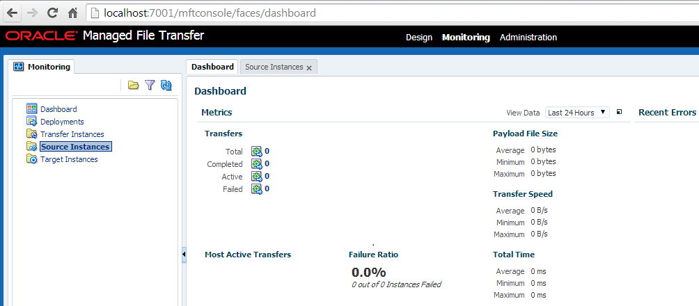
Let’s start with the exercise, first open the MFT console by going to (http://host:port/mftconsole) link. You will see below screen, at the top you can see three links. Design link is used by developer to do define required parameters to transfer the file. Monitoring link is used to monitor the file transfer and administration link is used for administration purpose.

MFT Screen


Click on Design link and now we define the source parameters where we place the sample file and MFT pick it from here. As mentioned earlier we are using local folder for source so we give source a name and choose “File” from drop down list. You also need to specify folder path.
MFT Define Source

As shown in below screen shot, you can also set advance properties for source.

MFT Source Advance Properties

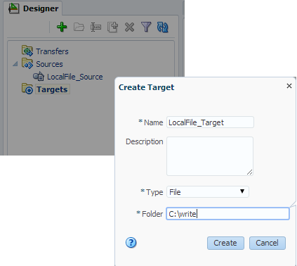
Now as we define the source, define the target as well. We again choose file from drop down list and provide the folder path. As mentioned above again we use local folder for target so MFT will pick the file from source path and place it at target folder.

MFT Target

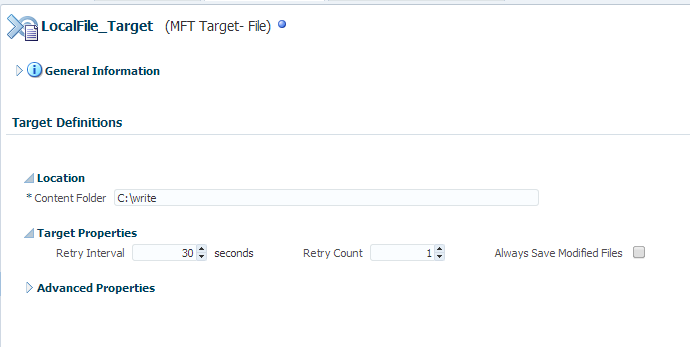
As shown in below screen shot, you can set advance properties for target.

MFT Target Advance properties

Once you define the source and target, next step is to define the transfer. In ransfer, first provide the transfer name, note that transfer name should be meaningful, it should be like , we can easily recognize what are source and target points involved in this transfer. Click on create, you will see transfer definition screen pops up. In this screen we choose required source and target.  

MFT Create Transfer

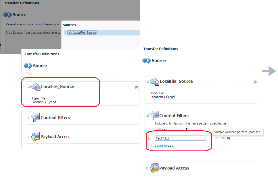
In above screen, click on add source link and choose above created source. Now we need to specify the file name which we need to read from source folder. To do that click on content filters and choose wildcard from dropdown and specify file wildcard pattern.


Define MFT Transfer
Now we choose target, to do that click on add target link and choose before created target.

Select target for MFT Transfer
Now we need to define the schedule, this schedule triggers the MFT transfer from source to target. To define the schedule click on add schedule link and fill required scheduling details. 

Define MFT Transfer Schedule

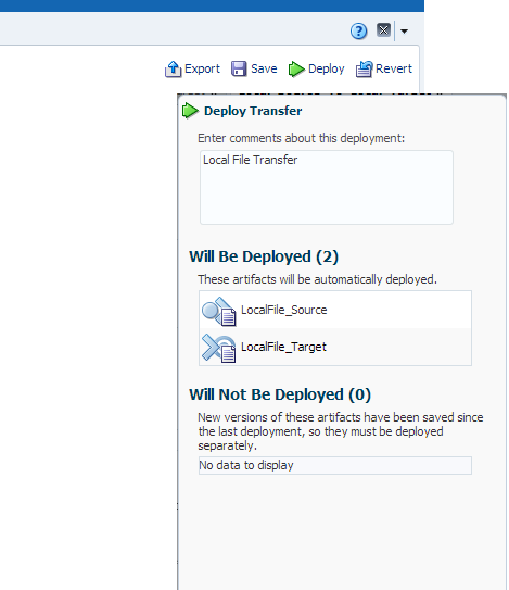
Once done click on save, now next step is to deploy newly created MFT transfer to server. This will enlist all the artifacts which will get deployed to the server.

Deploy MFT

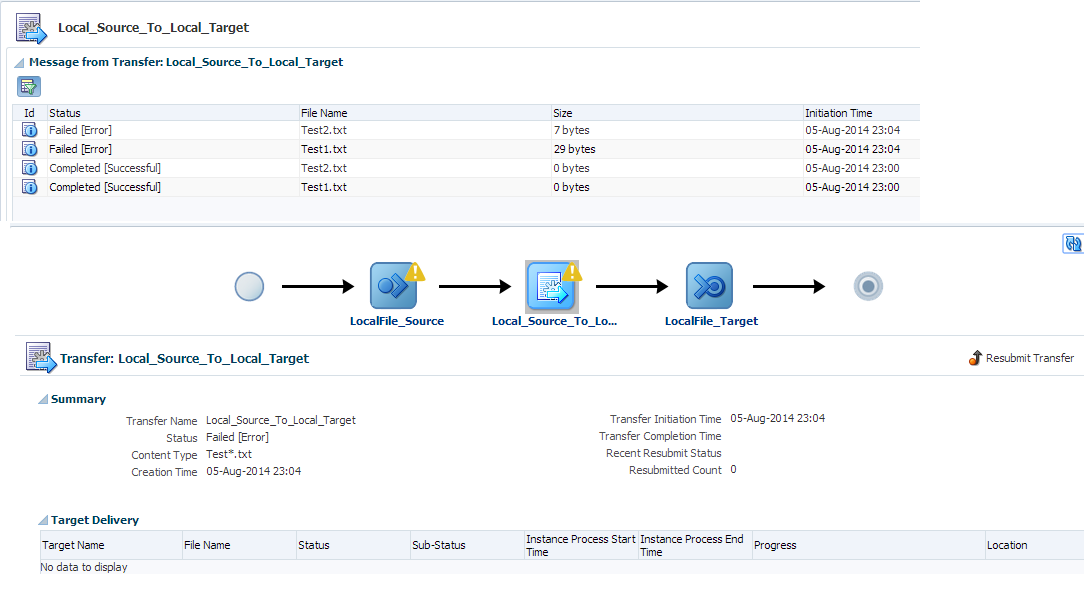
Now place the file at source folder and this file should be picked by MFT to transfer it to target folder. You can also monitor this file transfer, to do click on Monitoring tab as shown in below diagram and choose the transfer instance which you want to monitor.

MFT Monitoring

As you can see in below screen shot , file transfer got failed and below screen show the file transfer status. There is also one option to re-submit the file transfer.


MFT Testing


Thursday, October 16, 2014

SOA 12c - Design Fault Policy from Fault Policy Wizard

Fault handling framework is used to handle faults using fault policy and fault binding files. In earlier version of SOA suite which was 11g, we have to create these files manually. There was no provision to create these files from any wizard. Manual process is always error prone and it is quite difficult to remember all fault names and actions which we need to use in fault policy file. Oracle came up with fault policy wizard in SOA 12c, we can use that fault policy wizard to create fault policy file to handle faults in composite. This makes it less error prone and more productive. In this post, we will see how to create fault policy file from fault policy wizard and how to link it to fault binding file.

For this post, we have created a sample composite which invokes one target service. When we shutdown the target service then remote fault gets generated in sample composite which invokes target service. We will handle that remote fault in fault policy file and using alert send that message to JMS queue.

To create fault policy file, right click on the project and click on New àFrom Gallery. Choose Faults option under SOA Tier and select Fault Policy Document to create new fault policy file.

Create Fault Policy File


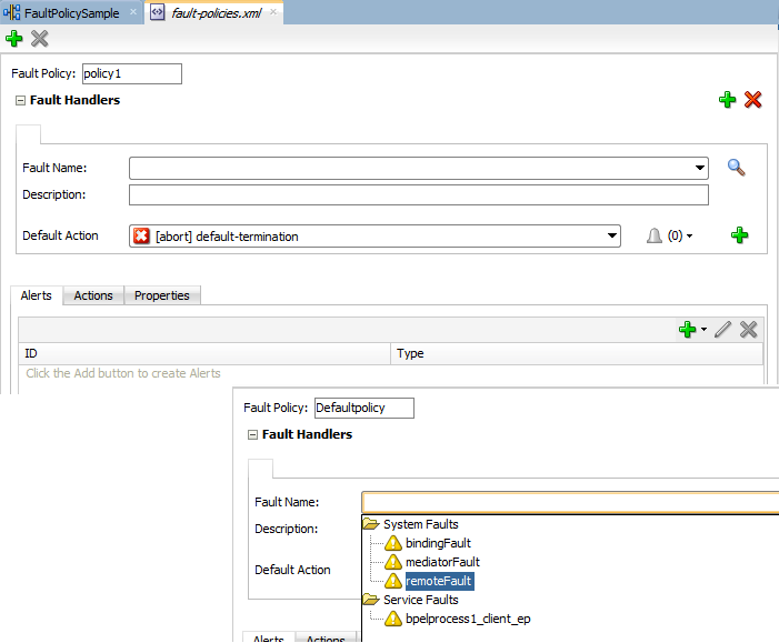
You can change the fault policy name from default “policy1” to any name as per your naming standards. You can choose the Fault Name which you need to handle in this fault policy, you can handle multiple faults in one policy, to add additional fault name you can click on Green plus sign. You can also change the default action from drop down list. We renamed the policy file and choose remoteFault as a fault name as we are going to handle this fault using fault policy file.

Fault Policy Name and Default Action


Now we will choose the alert which gets triggered when that fault occur. This is the additional feature provided in fault policy file. There are three types of alerts (email, JMS and Log) provided. We will create JMS alert for this post so choose JMS from the list. Provide the alert name and click on “Create Required Properties” tab to create required property set for JMS alert. Provide the property set name and specify required properties for JMS queue, once done click on Ok.

Create JMS Alert


Now we link above created alert to default action so whenever remote fault occur, process get terminated as a default action and message gets populated to JMS queue as JMS alert.

Link JMS Alert to Default Action


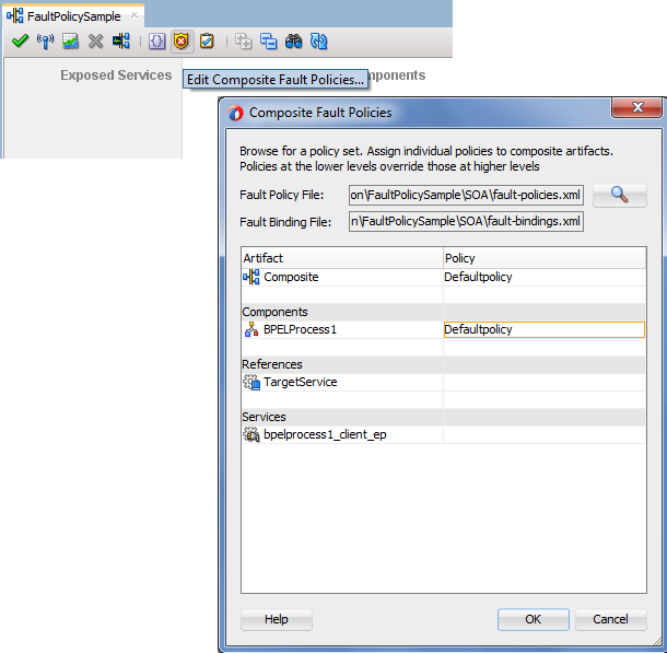
With the above step you are done with fault policy creation from fault policy wizard, now we will create fault binding file and link this fault policy file to composite, components, services and references.

Click on highlighted icon and bind the fault policy file to required components, services and references.

Llink Fault Policy file to Fault Binding


Now deploy your composite and test it. Make sure target service is down so that remote fault gets generated. That remote fault will be handled by fault policy file, it terminate the instance and send the message to JMS queue.


Thursday, October 9, 2014

SOA 12c - Encryption and Decryption of Sensitive Data

Oracle SOA Suite is used for reliable transfer of information, it stores whole the message in SOA_INFRA schema. We can see incoming and outgoing messages in audit trail from EM console. That means user which has access to EM console can see all the messages coming and going through middleware, sometimes some of the information which is flowing through Oracle SOA Suite is very critical and SOA Suite user should not have access to see that critical piece of information. In this post we will discuss how to fulfill this requirement using Oracle SOA Suite.

In previous version of Oracle SOA Suite (11g) there were no out of box provision to encrypt and decrypt sensitive data so user can see the data which is flowing through fusion but in current version of Oracle SOA Suite which is 12c, Oracle provided out of box functionality to encrypt specific fields in the message which is flowing through middleware. Below is sample encrypted message field.

Sample Encrypted Data


In Oracle SOA 12c, encryption policy is used to encrypt and decrypt the message, message encryption happens at component binding that means message get encrypted before it come to component (BPEL or Mediator) and we see only encrypted message in audit trail. Message decryption happens at reference binding level that means message fields get decrypted before it is sent to target service/system.

Encrypting Sensitive Data Flow


Let’s see in detail how to encrypt and decrypt a specific field in message.  For this post we have created a target service which is noting a SOA composite, we also created another SOA composite (Sales Order Composite) where we perform data encryption and decryption. Sales Order composite invokes target service. Sales Order composite receives message from source system and it contain below shown fields in the message. From these fields “Quantity” field is critical and we don’t want to show actual value for this field in EM console so we encrypt this field in this post.
Encrypting Sensitive Sample Composite


How to encrypt sensitive field

To do encryption, right click on the source bindings and choose “Encrypt Sensitive Data”. This open another pop-up where you can see out of box policy used for the encryption. Click on the edit button so that we can define the message field which we want to encrypt.

Encrypting Sensitive Data Reference Binding


Once you click on the edit button, this opens another window. Click on plus sign to choose the required field which we need to encrypt. For this post, we encrypt quantity field. Once done click on next, now we need to provide CSF-key value, by default it choose “pii-csf-key”. Click on finish.

Specify Sensitive data


Make sure pii-csf-key should exist, if it does not exist then you will not be able to encrypt the message and see error message. Click here to see how to create csf-key.

Encrypting Sensitive Data CSF-Key


How to decrypt sensitive field

As mentioned earlier in the post, field decryption happens at reference binding level. To perform decryption, right click on the reference binding and choose “Decrypt Sensitive Data”. This open another window where you can see the out of box policy used for decryption, click on edit sign and choose the field which you need to decrypt. Also choose the default csf-key.

Decrypt Sensitive Data


Save your composite and deploy it to the server.

Testing Results

Now test your sales order composite, once you open the sales order composite instance and open the audit trail for receive activity, you see quantity field is encrypted.

Encrypting Sensitive Data Testing


Now let’s open the target service instance. As you can see in below screen shot, field decryption happens at sales order composite reference binding level and quantity field is passed to target service in plain text.

Encrypting Sensitive Data Testing Result


Download sample code from here.